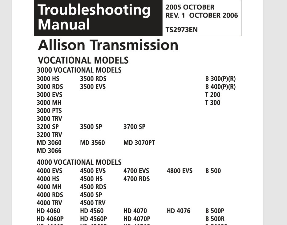
Allison WTEC III Service Manual PDF: Essential Guide for Heavy Truck Maintenance

The Allison WTEC III Service Manual PDF is a vital resource for understanding and maintaining the WTEC III electronic control system used in heavy truck transmissions. It provides comprehensive information on wiring schematics, core components, and troubleshooting techniques. This manual serves as a guide for technicians to effectively work with the system and ensures optimal performance and reliability of the transmissions. Access to this manual can significantly enhance maintenance efficiency for heavy-duty vehicles.
- Overview of Allison WTEC III System
- Understanding the Wiring Schematics
- Core Components of WTEC III
- Working with the ECU
- Troubleshooting Manual for Common Issues
- Tools and Equipment for Maintenance
- Maximizing Transmission Performance
- Accessing the Service Manual PDF
- Allison WTEC III Service Manual PDF
Overview of Allison WTEC III System
The Allison WTEC III system represents a significant advancement in the control of automatic transmissions for heavy-duty vehicles. It integrates multiple functions into a cohesive electronic control unit, enhancing both performance and efficiency.
Purpose and Applications
This sophisticated system is essential for managing the complex functionalities of transmissions used in various heavy truck applications. Specifically designed for Allison's 3000 and 4000 series transmissions, the WTEC III system streamlines operations and provides improved diagnostics for maintenance.
The core purpose of this system is to facilitate optimal engine and drivetrain performance, resulting in enhanced vehicle handling and reduced fuel consumption. Common applications include:
- Commercial trucks
- Bus systems
- Construction vehicles
- Agricultural machinery
The versatility of the WTEC III allows for its deployment across different industries, making it a vital component in heavy vehicle fleets.
Key Features
Allison's WTEC III system incorporates several key features that contribute to its reliability and effectiveness in transmission management. These features include:
- Electronic Control: The system employs advanced electronic controls to monitor various parameters, ensuring precise operation under diverse conditions.
- Sensors Integration: Multiple sensors are integrated into the system to monitor critical variables such as speed, temperature, and pressure, allowing for real-time adjustments.
- Diagnostics Capabilities: Built-in diagnostic tools help identify issues quickly, reducing downtime and improving maintenance schedules.
- Shift Optimization: The system optimizes shifting patterns based on driving conditions, enhancing both performance and fuel efficiency.
The combination of these features not only increases the longevity of the transmission but also greatly improves the overall driving experience of the vehicle.
Understanding the Wiring Schematics
Wiring schematics play a crucial role in diagnosing and solving electrical issues in the Allison WTEC III system. They provide valuable insights into how various components are interconnected within the transmission system.
Connectors and Pin Configuration
Connectors serve as vital links between the different components of the Allison WTEC III system. Each connector is designed for specific functions, allowing for reliable communication and electrical flow.
Identifying Connectors
Recognizing the various types of connectors is essential for effective troubleshooting. The manual includes visual guides for identifying connectors used in the 3000 and 4000 series transmissions. Technicians must familiarize themselves with the shapes, sizes, and key markings of each connector. This knowledge aids in preventing incorrect connections, which can lead to operational failures.
Pin Layout and Functions
Each connector is further defined by its pin layout and functions. Detailed diagrams illustrate the arrangement of pins within these connectors. It’s crucial to understand the role of each pin, as miswiring can cause significant issues in transmission operations.
The pin layout typically contains:
- Power pins for supplying voltage to various sensors.
- Ground pins to ensure proper electrical grounding.
- Signal pins for transmitting data between the sensors and the ECU.
Knowing the specific function of each pin enables technicians to execute precise repairs and modifications when necessary.
Cable Colors and Abbreviations
Cable colors and the abbreviations used in wiring schematics provide additional guidance for technicians. A color-coded system helps quickly identify the purpose of each wire.
Common cable colors and their corresponding functions include:
- Red: Typically indicates power cables supplying voltage.
- Black: Commonly used for ground connections.
- Green: Often used for signaling between components.
Alongside color codes, abbreviations play a significant role in interpreting schematics. These abbreviations denote various wire types, functions, and connections critical for accurate installations and repairs. Mastery of this language within the schematic ensures that technicians can follow complex diagrams efficiently.
Core Components of WTEC III
The core components of the WTEC III system play a pivotal role in managing the transmissions of heavy vehicles. This section delves into the critical modules and sensors that ensure optimal functionality and efficiency during operation.
Transmission Control Modules
At the heart of the WTEC III system are the transmission control modules (TCM), which serve as the brain of the transmission system. These modules gather inputs from various sensors, process the data, and send commands to adjust the transmission's performance. The TCM is responsible for several key functions, including:
- Monitoring vehicle speed and engine performance
- Controlling shift patterns for smooth gear transitions
- Communicating with the Engine Control Unit (ECU) for coordinated operation
- Diagnosing faults within the transmission system
Given their critical role, the reliability and accuracy of TCMs are essential for maintaining transmission efficiency and prolonging system lifespan.
Essential Sensors in WTEC III
WTEC III relies on a collection of sensors that provide real-time data essential for effective control and performance optimization. These sensors monitor various parameters that influence transmission operation.
Engine Speed Sensor
The engine speed sensor measures the revolutions per minute (RPM) of the engine. This data is crucial for determining the appropriate shift points within the transmission. By providing accurate RPM readings, the sensor enables the TCM to make informed decisions, ensuring that the engine operates at optimal efficiency.
Turbine Speed Sensor
This sensor tracks the speed of the turbine within the transmission. By measuring the turbine’s rotation rate, it allows for adjustments that enhance power transfer and improve shift quality. The turbine speed sensor ensures that shifts occur at the right moment, maximizing performance and minimizing wear on transmission components.
Output Speed Sensor
Positioned at the output of the transmission, this sensor measures the speed of the output shaft. Its readings are vital for delivering precise information about the vehicle's speed and performance characteristics. The output speed sensor feeds data back to the TCM, aiding in maintaining the correct power delivery to the driveline while ensuring smooth operation under varying load conditions.
Working with the ECU
Understanding the interaction and calibration of the ECU is essential for optimal sensor functionality and transmission performance.
Interaction Between Sensors and ECU
The Electronic Control Unit (ECU) serves as the brain of the Allison WTEC III system, coordinating data from various sensors to manage transmission operations effectively. The seamless communication between these sensors and the ECU is critical for maintaining performance and reliability.
- Data Reception: The ECU continually receives inputs from multiple sensors, including engine speed, turbine speed, and output speed sensors. This data is processed to make real-time adjustments to transmission behavior.
- Signal Processing: Upon receiving data, the ECU interprets the signals using predefined algorithms. It leverages this information to optimize shifting patterns and transmission fluid pressure.
- Error Detection: The ECU is also responsible for monitoring sensor performance. If it detects a discrepancy or failure in one of the sensors, it generates error codes that can be read by diagnostic tools.
ECU Calibration and Troubleshooting
Proper calibration of the ECU is crucial to ensure that it operates efficiently and responds accurately to the inputs from the sensors. Calibration and troubleshooting procedures require careful attention to detail.
- Calibration Procedures: Calibration involves setting the ECU to adjust various parameters based on the specific application and vehicle conditions. This process may require specialized software or diagnostic equipment.
- Common Troubleshooting Steps:
- Sensor Verification: Check the integrity and function of each sensor to ensure they are sending accurate data to the ECU.
- Connection Checks: Inspect wiring harnesses and connectors for signs of wear or damage that could disrupt signal transmission.
- ECU Reset: If persistent faults occur, resetting the ECU may help clear errors and restore normal operation.
Each of these methods is integral to bringing the ECU back to a suitable operating state, thus contributing directly to the overall performance of the transmission system.
Troubleshooting Manual for Common Issues
This section provides comprehensive guidance for addressing frequent issues that may arise within the WTEC III control system.
Diagnosing Sensor Connection Failures
Failures in sensor connections are common sources of trouble in the WTEC III system. Ensuring all connections are secure and intact is essential for optimal performance.
- Check for loose or damaged connectors. A visual inspection can often reveal wear or corrosion on contact points.
- Test each sensor's continuity using a multimeter. This will confirm whether the sensor is functioning properly or if it requires replacement.
- Verify that all wiring adheres to specified pin layouts. Incorrect configurations can lead to misreadings and system faults.
Resolving ECU Malfunctions
ECU malfunctions can severely impact the functionality of the WTEC III system. Identifying and addressing these issues is crucial.
- Inspect all connections to the ECU for any signs of damage or corrosion. Poor connections can prevent the ECU from receiving accurate signals.
- Perform a reset of the ECU. Sometimes, simply restarting the system can clear temporary faults.
- Utilize diagnostic tools to read error codes generated by the ECU. These codes will provide specific insight into the nature of the malfunction.
Addressing Communication Problems
Effective communication between sensors and the ECU is paramount for the performance of the WTEC III system. Disruptions can lead to operational inefficiencies.
- Check for any disruptions in the wiring harnesses that could affect communication signals. Look for abrasions or kinks in the wires.
- Examine the integrity of connectors along the signal path. Faulty connectors can disrupt expected data flow between components.
- Test each sensor separately to determine if data transmission to the ECU is functioning correctly. This helps isolate the problem to specific components.
Tools and Equipment for Maintenance
Having the right tools and equipment is essential for maintaining the Allison WTEC III system effectively. A well-equipped workshop enables technicians to perform diagnostics, repairs, and maintenance tasks efficiently, ensuring optimal performance of heavy trucks.
Electronic Diagnostic Tools
Utilizing electronic diagnostic tools enhances the capability to troubleshoot and maintain the WTEC III system. These tools are designed to interact with the electronic components, allowing technicians to identify issues quickly.
Using a Multimeter
A multimeter is an invaluable tool for electrical diagnostics, providing the ability to measure voltage, current, and resistance. Using a multimeter involves:
- Selecting the appropriate setting for the measurement type.
- Probing the circuits or connectors to obtain readings.
- Interpreting the results to diagnose potential electrical issues.
By understanding the voltage levels and continuity within the system, technicians can pinpoint problems related to sensors and wiring, ensuring the integrity of the WTEC III components.
Reading Error Codes
Error codes provide critical information regarding the status of the WTEC III system. Diagnostic tools often come with the capability to read these codes, which are stored in the ECU. Key actions include:
- Connecting the diagnostic tool to the vehicle's OBD-II or specific connector.
- Navigating the tool's interface to retrieve stored codes.
- Consulting the service manual to interpret each code accurately.
This process helps technicians isolate issues, allowing for a targeted approach to repairs, ultimately improving the system's efficiency.
Recommended Technical Resources
Resources tailored for technical support are essential for maintaining the Allison WTEC III system. Access to current manuals and documentation ensures that technicians are informed about the latest updates and practices.
- WTEC III service manuals in PDF format provide a comprehensive guide for diagnostics and repair procedures.
- Online forums and communities serve as platforms where technicians share experiences and solutions, fostering a collaborative environment for learning.
- Manufacturer's resources offer technical bulletins and product updates that keep technicians aware of modifications and enhancements to the WTEC III system.
Utilizing these resources supports technicians in developing their skills and achieving a higher level of proficiency in maintenance tasks. Being well-informed enhances the reliability and performance of the WTEC III-equipped vehicles.
Maximizing Transmission Performance
Effective management and maintenance of the transmission system are key to optimizing vehicle performance. Maximizing transmission performance not only enhances operational efficiency but also plays a crucial role in extending the lifespan of the transmission components.
Importance of Regular Maintenance
Consistent maintenance routines are essential for preserving the integrity of the WTEC III transmission system. Regular checks and services facilitate early detection of potential issues and can mitigate severe problems that may arise from neglect.
- Ensures functional integrity of the transmission system.
- Reduces the likelihood of unexpected downtimes.
- Improves fuel efficiency through optimized performance.
- Enhances the overall safety of the vehicle.
Many transmission issues stem from a lack of attention to regular maintenance. Components such as filters, fluid levels, and wiring should be routinely inspected for potential wear and tear. Performing such checks helps keep the system in optimal working condition.
Enhancing Efficiency and Safety
Enhancing efficiency involves not only regular maintenance but also implementing best practices in operating the vehicle. Efficient operation reduces wear on the transmission system and leads to better overall performance.
- Utilizing appropriate driving techniques can prevent excessive strain on the transmission.
- Making use of the correct type of transmission fluid will ensure proper functioning and longevity.
- Monitoring sensor readings regularly for accurate performance data contributes to proactive maintenance.
For safety, routine checks of brake functions and other related systems are paramount, as they can impact transmission performance directly. Furthermore, understanding the relationship between transmission and other mechanical systems in the vehicle can lead to informed decisions that enhance overall vehicle safety. BR>
Overall, investing in the maintenance and operational efficiency of the transmission system is essential. A well-maintained WTEC III system will not only perform better but ultimately contribute to a safer and more reliable vehicle operation for the long term.
Accessing the Service Manual PDF
Accessing the Allison WTEC III Service Manual PDF is essential for effective maintenance and repairs. This manual provides crucial insights that enhance the lifespan and performance of the transmission systems used in heavy trucks.
Online Resources and Availability
A variety of online platforms offer access to the Allison WTEC III Service Manual PDF. These resources can significantly assist technicians and operators in finding the information they need quickly and efficiently.
- Specialized websites dedicated to heavy truck maintenance often host downloadable PDFs of service manuals.
- Online forums and communities may provide links or shared experiences related to accessing the manual.
- Many manufacturers and dealerships provide official downloads or guides to accessing digital versions of their service documentation.
- Some educational institutions and trade schools may offer access to these materials as part of their training programs.
Using the Manual for Effective Repairs
The Allison WTEC III Service Manual PDF is structured to facilitate effective repair and maintenance procedures. Proper utilization of this resource yields improved outcomes for transmission performance.
- Understanding wiring schematics is essential for diagnosing electrical issues.
- Familiarity with sensor descriptions allows technicians to pinpoint faults swiftly and accurately.
- Utilizing troubleshooting sections can save time when dealing with common problems, as these provide step-by-step instructions.
- Reviewing maintenance schedules and guidelines helps ensure that routines are followed to enhance reliability.
Equipping oneself with knowledge from the manual not only aids in immediate troubleshooting but also contributes to long-term vehicle care. Leveraging the information found within the manual encourages a standardized approach to repairs, ultimately leading to safer operation and improved vehicle efficiency.
Allison WTEC III Service Manual PDF
If you want to know other articles similar to Allison WTEC III Service Manual PDF: Essential Guide for Heavy Truck Maintenance you can visit the category TRUCK MANUALS.


Leave a Reply