Cummins CM2350 wiring diagram

The Cummins CM2350 wiring diagram is a crucial tool for anyone working with Cummins engines, particularly the ISX15 and ISB6.7 models. Understanding this diagram is essential for effective troubleshooting and maintenance. In this article, we will explore the various aspects of the Cummins CM2350 wiring diagram, detailing its components, how to read it, and where to find it.
- What is the Cummins CM2350 wiring diagram?
- How to read the Cummins CM2350 wiring diagram?
- What are the key components in the Cummins CM2350 wiring diagram?
- How to troubleshoot using the Cummins CM2350 wiring diagram?
- Where to find the Cummins CM2350 wiring diagram PDF?
- What are the common issues related to the Cummins CM2350 wiring diagram?
- Questions related to the Cummins CM2350 wiring diagram
What is the Cummins CM2350 wiring diagram?
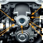
The Cummins CM2350 wiring diagram provides a comprehensive representation of the electrical connections within Cummins engines. This diagram is especially important for technicians, as it outlines the various components and their interconnections.
In essence, the cummins cm2350 wiring diagram displays how each sensor and actuator connects to the engine's electronic control unit (ECU). By utilizing this diagram, technicians can identify wiring layouts and troubleshoot potential electrical issues effectively.
Additionally, the diagram includes important symbols and labeling that aid in understanding the electrical circuits. This makes it easier to interpret the data during diagnostics or repairs, ultimately improving the operational efficiency of the engine.
How to read the Cummins CM2350 wiring diagram?
Reading the Cummins CM2350 wiring diagram requires familiarity with various electrical symbols and terminologies utilized within the diagram. Each symbol represents specific components, such as sensors, solenoids, and connectors.
To begin reading the diagram, start by familiarizing yourself with the key symbols used. For instance, a crankshaft position sensor and a camshaft position sensor will have unique symbols that distinguish them from other components.
Next, trace the wiring lines connecting these components to the ECU. Each line indicates the type of electrical connection, whether it's a signal wire, ground, or power supply. Understanding these connections is vital for troubleshooting any issues related to the electrical system.
For a more efficient reading experience, it’s advisable to have a magnifying glass handy, as some diagrams feature intricate details that may be hard to distinguish at first glance.
What are the key components in the Cummins CM2350 wiring diagram?
The Cummins CM2350 wiring diagram includes several essential components that play a significant role in the engine's functionality.
- Crankshaft Position Sensor: This sensor helps in determining the position of the crankshaft, which is critical for timing and fuel injection.
- Camshaft Position Sensor: Similar to the crankshaft sensor, this component monitors the camshaft position for optimal engine performance.
- Intake Manifold Pressure Sensor: This sensor measures the pressure within the intake manifold, providing data to the ECU for fuel management.
- Injector Solenoid: The injector solenoid controls the fuel injection process, ensuring that the engine receives the correct amount of fuel.
- Electrical Circuit Diagram: This is a visual representation of the electrical connections, providing a roadmap for troubleshooting.
Each of these components is crucial for maintaining the engine's performance and ensuring compliance with emissions standards. By using the wiring diagram, technicians can ensure that these key components function correctly within the overall electrical system.
How to troubleshoot using the Cummins CM2350 wiring diagram?
Troubleshooting with the Cummins CM2350 wiring diagram involves a systematic approach to diagnosing electrical issues. Begin by reviewing the symptoms reported by the engine operator or observed during operation.
First, consult the wiring diagram to identify which components are involved in the reported issues. By tracing the wiring connections, you can determine if there are any breaks or shorts in the wiring.
Next, utilize a multimeter to check the voltage and continuity of the wiring. Ensure that the readings match the specifications indicated in the wiring diagram. If discrepancies are found, repairs or replacements may be necessary.
Additionally, cross-reference the wiring diagram with the engine's fault codes. Many modern Cummins engines use an onboard diagnostic system that can provide error codes related to electrical issues. Analyzing these codes in conjunction with the wiring diagram will help narrow down potential problems.
Where to find the Cummins CM2350 wiring diagram PDF?
Finding the cummins cm2350 wiring diagram pdf can be done through several avenues. The most reliable source is the official Cummins website, where they provide technical documentation for their engines, including wiring diagrams.
You can also check with authorized Cummins dealers or service centers. They often have access to the latest manuals and diagrams, which they can provide upon request.
Another option is to explore online forums and communities dedicated to Cummins engines. Many professionals share resources and documentation that can be invaluable for both troubleshooting and learning. Websites like Scribd and various automotive repair sites may also host these PDFs.
Lastly, consider joining industry-specific groups on social media platforms where members regularly share useful resources, including wiring diagrams.
Several common issues can arise when dealing with the Cummins CM2350 wiring diagram. Recognizing these problems can expedite the troubleshooting process.
- Wiring Shorts: A frequent issue is shorts in the wiring harness, which can lead to circuit malfunctions and affect engine performance.
- Connector Issues: Corrosion or damage to connectors can result in poor electrical connections, leading to inconsistent readings from sensors.
- Faulty Sensors: Sensors such as the crankshaft and camshaft position sensors can fail, causing erroneous data that may lead to incorrect fuel injection.
- Grounding Problems: Poor grounding connections can create a variety of problems, including erratic engine behavior and failure to start.
Being aware of these common issues will help technicians diagnose problems more efficiently and accurately. Utilizing the Cummins CM2350 wiring diagram can provide insights into potential electrical failures and repairs that may be necessary.
What is the Cummins CM2350 wiring diagram?
The Cummins CM2350 wiring diagram is a detailed representation of the electrical connections within Cummins engines. It is essential for understanding the various components and their interconnections, enabling technicians to diagnose and troubleshoot issues effectively.
How to read the Cummins CM2350 wiring diagram?
Reading the Cummins CM2350 wiring diagram involves familiarizing yourself with the symbols used for each component, tracing wiring lines, and understanding the connections to the ECU. This knowledge is crucial for effective troubleshooting.
What are the key components in the Cummins CM2350 wiring diagram?
Key components include the crankshaft position sensor, camshaft position sensor, intake manifold pressure sensor, and injector solenoid. These elements are integral to the engine’s performance and operational efficiency.
How to troubleshoot using the Cummins CM2350 wiring diagram?
Troubleshooting involves reviewing symptoms, identifying involved components via the wiring diagram, checking voltage and continuity, and cross-referencing with onboard diagnostic codes to narrow down issues.
Where to find the Cummins CM2350 wiring diagram PDF?
The Cummins CM2350 wiring diagram PDF can be found on the official Cummins website, through authorized dealers, online forums, and various automotive repair sites.
What are the common issues related to the Cummins CM2350 wiring diagram?
Common issues include wiring shorts, connector problems, faulty sensors, and grounding issues. Awareness of these problems can aid in quick and accurate troubleshooting.

If you want to know other articles similar to Cummins CM2350 wiring diagram you can visit the category CUMMINS.
Deja una respuesta
RELATED POSTS