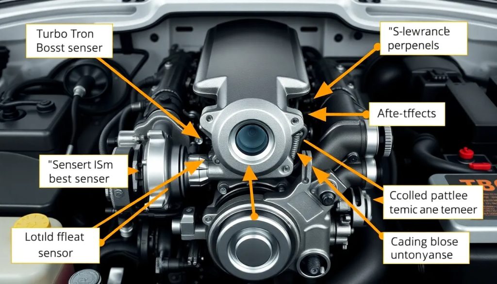
Cummins ism sensor location diagram

The Cummins ISM sensor location diagram is an essential tool for understanding the intricate wiring and connections within the ISM CM875 and CM876 engine models. This diagram is crucial for technicians working on these engines, as it simplifies complex electrical layouts and aids in troubleshooting.
Whether you are maintaining or repairing a Cummins ISM engine, having access to the sensor location diagram can enhance efficiency and ensure optimal performance. This article will delve into various aspects of the diagram and its significance for engine diagnostics.
- What is the cummins ism sensor location diagram?
- How to interpret the wiring diagram for cummins ism?
- What are the key components highlighted in the cummins ism diagram?
- How to use the cummins ism electrical circuit diagram for troubleshooting?
- What are the differences between cummins ism cm875 and cm876?
- Where can I find the detailed wiring information for cummins ism models?
- Related questions about cummins ism sensors and diagrams
What is the cummins ism sensor location diagram?
The Cummins ISM sensor location diagram provides a comprehensive view of the wiring and electrical systems involved in the ISM CM875 and CM876 engines. It outlines the positions of critical sensors, wire colors, and symbols representing different electrical components.
This diagram is not just a visual aid; it serves as a reference guide for technicians. By detailing the signal flow and power supply for each sensor, it enables users to understand how the engine's electronic control system functions.
Moreover, the diagram highlights important components, such as the turbocharger speed sensor and engine position sensor, ensuring that technicians can easily locate and address any issues that may arise.
How to interpret the wiring diagram for cummins ism?
Interpreting the wiring diagram for Cummins ISM requires a basic understanding of electrical components, symbols, and color coding. Each symbol in the diagram corresponds to a specific component within the engine's electrical system.
To effectively read the diagram:
- Identify symbols: Familiarize yourself with the common symbols used in electrical diagrams, such as resistors, capacitors, and sensors.
- Follow wire color codes: Different colors indicate different functions and connections. Understanding these can prevent errors during repairs.
- Trace signal flow: Follow the path of signals from sensors to the engine control unit (ECU) to identify any potential disruptions in the system.
By utilizing this approach, technicians can effectively diagnose problems within the Cummins ISM electrical system, leading to quicker and more accurate repairs.
What are the key components highlighted in the cummins ism diagram?
The Cummins ISM diagram highlights several key components that are vital for the engine's performance. Understanding these components is essential for effective maintenance and troubleshooting.
Some of the critical components included in the diagram are:
- Turbocharger speed sensor: This sensor monitors the speed of the turbocharger, playing a crucial role in optimizing engine performance.
- Engine position sensor: It determines the position of the engine's crankshaft, essential for timing and fuel injection.
- Fuel temperature sensor: This component ensures that the fuel is at the correct temperature for optimal combustion.
- Oil pressure sensor: It monitors the oil pressure within the engine, helping to prevent potential damage.
Each of these components communicates with the engine control unit (ECU), and understanding their functions helps technicians maintain and troubleshoot the Cummins ISM engines more effectively.
How to use the cummins ism electrical circuit diagram for troubleshooting?
Using the Cummins ISM electrical circuit diagram for troubleshooting involves a systematic approach to diagnosing issues. Here are some essential steps to follow:
First, ensure you have a clear understanding of the engine's electrical system. Familiarize yourself with the diagram and identify the sensors and connections relevant to the issue at hand.
Next, follow the signal path from the problematic component back to the ECU. This helps you pinpoint where the fault may lie, whether it be a broken wire, a faulty sensor, or an issue within the ECU itself.
Utilizing a multimeter can be beneficial during this process. Check for continuity at various points along the wiring to ensure there are no breaks or interruptions in the circuit. Additionally, verify that each sensor is receiving the correct voltage.
Lastly, refer to the troubleshooting guides that often accompany the diagrams. These guides provide valuable insights into common issues and their solutions, making the troubleshooting process more efficient.
What are the differences between cummins ism cm875 and cm876?
The Cummins ISM CM875 and CM876 engines, while similar, have key differences that affect their operation and applications. Understanding these differences is crucial for technicians working with these models.
One significant distinction is the model year range. The CM875 was manufactured between 2003 and 2006, while the CM876 was produced from 2007 to 2009. This change brought about updates in the engine's software and hardware.
Another difference lies in emissions standards. The CM876 is designed to meet stricter emissions regulations compared to its predecessor, leading to enhancements in fuel efficiency and reduced environmental impact.
Additionally, the Cummins ISM CM876 features improved turbocharging capabilities and sensor technologies, enhancing overall performance and reliability.
Where can I find the detailed wiring information for cummins ism models?
Finding detailed wiring information for Cummins ISM models can be crucial for any technician involved in maintenance or repairs. Several resources are available to assist in locating these diagrams.
One of the best sources is Cummins' official website, where they provide access to a range of service manuals and wiring diagrams. These documents often contain the most accurate and up-to-date information.
Additionally, various online forums and communities dedicated to Cummins engines offer shared resources. Members often post wiring diagrams and troubleshooting tips based on personal experiences.
Lastly, many automotive supply stores and libraries carry manuals that include wiring diagrams for Cummins ISM engines. Utilizing these resources can save time and enhance your understanding of the engine's electrical layout.
Where is the engine position sensor on a Cummins ISM?
The engine position sensor on a Cummins ISM is typically located near the crankshaft, allowing it to accurately gauge the engine's position. This sensor plays a vital role in the engine's timing and fuel injection processes.
To locate it, refer to the wiring diagram, which will indicate its exact position. Generally, it is mounted on the engine block and is easily accessible for inspection and replacement.
Where is the boost pressure sensor on a Cummins ISM?
The boost pressure sensor on a Cummins ISM is usually situated on the intake manifold. It monitors the boost pressure produced by the turbocharger and sends this information to the engine control unit (ECU).
This sensor is crucial for maintaining optimal performance and ensuring that the turbocharger is functioning effectively. Technicians can use the wiring diagram to find its precise location during troubleshooting.
What is the difference between Cummins ISM and ISL?
The primary difference between the Cummins ISM and ISL engines lies in their design and intended applications. The ISM is often used in heavier-duty applications, while the ISL is designed for medium-duty vehicles.
Additionally, the ISM typically offers higher horsepower and torque ratings compared to the ISL, making it suitable for more demanding tasks. Each engine also has its own unique set of wiring diagrams and sensor locations, which technicians must be aware of for effective maintenance.
How many HP is a Cummins ISM?
The Cummins ISM engine typically ranges from 300 to 500 horsepower, depending on the specific model and configuration. This range allows it to perform well in various heavy-duty applications, providing powerful performance when needed.
Factors such as tuning and the presence of additional components can affect the horsepower output. It's essential for technicians to know these details when working with different Cummins ISM models.
 Detroit Diesel Series 60 Service Shop Manual Free Download
 Eaton ServiceRanger diagnostics software: everything you need to know
 CLARK GT30 50 60E GAS service manual
If you want to know other articles similar to Cummins ism sensor location diagram you can visit the category CUMMINS.
Deja una respuesta

RELATED POSTS